Large variety of available nominal sizes allows exact adjustment to the application
High power density
Very high total efficiency
High starting efficiency
Working ports SAE flange or thread
Optional with integrated pressure relief valve
Optional with mounted additional valve: counterbalance valve (BVD/BVE), flushing and boost-pressure valve
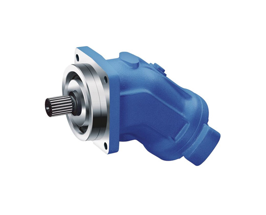
Bent-axis design


Notice
● Please note the project planning notes in chapter Project planning notes
● Please note that not all type code combinations are available although the individual functions are marked as being available
Technical data (theoretical value,not considering ηV andηmh , rounded values)


Size 5

Drive shafts

Ports

Size 10 … 16

Drive shafts Z and A

Drive shafts P and B

Port plate 03
Threaded ports at side, opposite

Port plate 04
Threaded ports at side and rear

Ports

Size 23 … 180

Drive shafts Z and A

Splined shaft DIN 5480

Drive shafts P and B

Parallel keyed shaft DIN 6885

Port plate 01
SAE working ports at rear

Port plate 02
SAE working ports at side, opposite

Port plate 10
SAE working ports at bottom

Note
● The dimensional drawings of the port plates with valves can be found in the chapter "Extended functions and versions".
Ports

Size 200

Drive shafts

Ports

Size 250

Drive shafts

Port plate 01
SAE working ports at rear

Port plate 02
SAE working ports at side, opposite

Ports

Size 355 … 1000


Drive shaft Z

Splined shaft DIN 5480

Drive shaft P

Parallel keyed shaft DIN 6885

Ports

Installation information
General information
● During commissioning and during operation, the axial piston unit must be filled with hydraulic fluid and bled. This must also be observed during longer standstill as the axial piston unit might drain itself via the hydraulic lines.
● Complete filling and bleeding must especially be ensured with the “Drive shaft upwards” installation position as there is, for example, the risk of running dry.
● The leakage in the housing area must be discharged to the tank via the highest-located drain port (T1, T2).
● If one joint drain line is used for several units, it is to be ensured that the relevant housing pressure is not exceeded. The joint drain line must be dimensioned so that the maximum admissible housing pressure of all connected units is not exceeded in any operating state, particularly during cold start. If this is not possible, separate drain lines have to be laid, if necessary.
● In order to achieve favorable noise values, all connection lines are to be decoupled using elastic elements and over-tank installation is to be avoided.
● The tank line must lead into the tank below the minimum liquid level in every operating state.
Installation position
See the following examples 1 to 8.
Further installation positions are possible upon request. Recommended installation position: 1 and 2.
Note
For installation position 4 and 8 "shaft upwards" an air bleed port R is required (specify in plain text when ordering, special version).
Below-tank installation (standard)
Below-tank installation is at hand if the axial piston unit is installed below the minimum liquid level outside the tank.

Above-reservoir installation
Above-reservoir installation means that the axial piston unit is installed above the minimum fluid level of the reservoir.
Recommendation for installation position 8 (drive shaft upward): A check valve in the drain line (cracking pressure 0,5 bar) can prevent draining of the pump housing.


General project planning notes
● The axial piston motor is designed to be used in open and closed circuits.
● The project planning, installation and commissioning of the axial piston unit require the involvement of qualified skilled personnel.
● Before using the axial piston unit, please read the corresponding instruction manual completely and thoroughly. If necessary, request it from Bosch Rexroth.
● Before finalizing your design, request a binding installation drawing.
● The specified datas and notes must be observed.
● Preservation: Our axial piston units are supplied as standard with preservative protection for a maximum of 12 months. If longer preservative protection is required (maximum 24 months), please specify this in plain text when placing your order. The preservation times are valid under optimal storage conditions. Details of these conditions can be found in the data sheet 90312 or the instruction manual.
● Not all versions of the product are approved for use in a safety function according to ISO 13849. Please consult the responsible contact person at Bosch Rexroth if you require reliability parameters (e.g. MTTFD) for functional safety.
● A pressure relief valve is to be provided in the hydraulic system.
● Observe the instructions in the instruction manual regarding tightening torques of connection threads and other threaded joints used.
● The notes in the instruction manual on tightening torques of the port threads and other screw joints must be observed.
● The ports and fastening threads are designed for the permissible maximum pressure pmax (see instruction manual). The machine or system manufacturer must ensure that the connecting elements and lines correspond to the specified operating conditions (pressure, flow, hydraulic fluid, temperature) with the necessary safety factors.
● The working ports and function ports are designated only to accommodate hydraulic lines.
● During and shortly after operation, there is a risk of burns on the axial piston unit. Take appropriate safety measures (e.g. by wearing protective clothing).
● In certain conditions, moving parts in high pressure relief valves might get stuck in an undefined position due to contamination (e.g. contaminated hydraulic fluid). This can result in restriction or loss of load holding functions in lifting winches. Therefore it is the machine and/or system manufacturers responsibility to make sure that the load can always be put in a safe mode if needed. Also, he needs to ensure that these measures are properly implemented.