

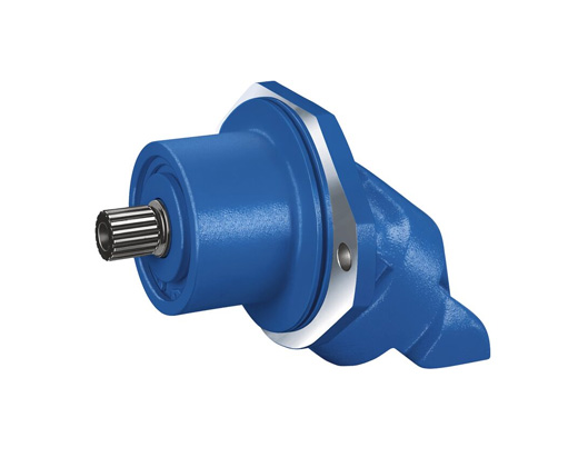
Space-saving construction due to recessed mounting flange
Easy to install, simply slide into the mechanical gearbox
High power density
Very high total efficiency
High starting efficiency
Optional with integrated pressure relief valve
Optional with mounted additional valve: counterbalance valve (BVD/BVE), flushing and boost-pressure valve
Bent-axis design


Notice
● Please note the project planning notes in chapter Project planning notes
● Please note that not all type code combinations are available although the individual functions are marked as being available
Table of values

Note
● The values in the table are theoretical values, without consideration of efficiencies and tolerances. The values are rounded.
● Exceeding the maximum or falling below the minimum permissible values can lead to a loss of function, a reduction in operational service life or total destruction of the axial piston unit. Other permissible limit values, such as speed variation, reduced angular acceleration as a function of the frequency and the permissible angular acceleration at start (lower than the maximum angular acceleration) can be found in data sheet 90261.
Speed range
No limit to minimum speed nmin. If uniformity of motion is required, speed nmin must not be less than 50 rpm.

Hydraulic fluids
The axial piston unit is designed for operation with mineral oil HLP according to DIN 51524.
Application instructions and requirements for hydraulic fluids should be taken from the following data sheets before the start of project planning:
● 90220: Hydraulic fluids based on mineral oils and related hydrocarbons
● 90221: Environmentally acceptable hydraulic fluids
● 90222: Fire-resistant, water-free hydraulic fluids (HFDR, HFDU)
● 90223: Fire-resistan, water-containing hydraulic fluids (HFAE, HFAS, HFB, HFC)
● 90225: Restricted technical data for operation with fire-resistant hydraulic fluids
Viscosity and temperature of hydraulic fluids

Note
To reduce high temperature of the hydraulic fluid in the axial piston unit we recommend the use of a flushing and boost pressure valve (see chapter Extended functions and versions).
Selection of hydraulic fluid
Bosch Rexroth evaluates hydraulic fluids on the basis of the Fluid Rating according to the technical data sheet 90235.
Hydraulic fluids with positive evaluation in the Fluid Rating are provided in the following technical data sheet:
● 90245: Bosch Rexroth Fluid Rating List for Rexroth hydraulic components (pumps and motors)
The hydraulic fluid should be selected so that the operating viscosity in the operating temperature range is within the optimum range (νopt; see selection diagram).
Selection diagram

Filtration of the hydraulic fluid
Finer filtration improves the cleanliness level of the hydraulic fluid, which increases the service life of the axial piston unit.
A cleanliness level of at least 20/18/15 is to be maintained according to ISO 4406.
At a hydraulic fluid viscosity of less than 10 mm²/s (e.g. due to high temperatures in short-term operation) at the drain port, a cleanliness level of at least 19/17/14 according to ISO 4406 is required.
For example, the viscosity is 10 mm²/s at:
● HLP 32 a temperature of 73°C
● HLP 46 a temperature of 85°C
Operating pressure range

Note
●Working pressure range valid when using hydraulic fluids based on mineral oils. Values for other hydraulic fluids, please contact us.
Minimum pressure at inlet (pump operating mode)

This diagram is only valid for the optimum viscosity range of vopt = 16 to 36 mm2/s.
If the above mentioned conditions cannot be ensured, please contact us.
Pressure definition


Rate of pressure change

Maximum differential pressure at the shaft seal

Note
● The service life of the shaft seal is influenced by the speed of the axial piston unit and the case pressure.
● The service life decreases with an increase of the mean differential pressure between the case and the ambient pressure and with a higher frequency of pressure spikes.
● The case pressure must be equal to or higher than the ambient pressure.
Direction of flow

Permissible radial and axial forces of the drive shaft

General instructions
● The values given are maximum values and do not apply to continuous operation.
● The axial force in direction −Fax is to be avoided as the service life of the bearing is reduced.
● Special requirements apply in the case of belt drives. Please contact us.
Notes for sizes 250 ... 355:
● In case of radial forces limited performance data is valid. Please contact us.
● In case of axial forces during operation of the unit please contact us.
Effect of radial force Fq on the service life of bearings
By selecting a suitable direction of radial force Fq the load on the bearings caused by the internal rotary group forces can be reduced, thus optimizing the service life of the bearings. Recommended position of mating gear is dependent on direction of rotation. Examples:
Toothed gear drive, size 28 … 180

Toothed gear drive, size 250 … 355

Long-Life bearing

Sizes 250 and 355
For long service life and use with HF hydraulic fluids. Identical external dimensions as version with standard bearings. Subsequent conversion to long-life bearings is possible.
Size 28 ... 180
Port plate 10


Note
The dimensional drawings of the port plates with valves can be found in the chapter "Extended functions and versions".
Drive shafts Z and A

Splined shaft DIN 5480

Ports

Size 250


Ports

Size 355


Ports

Installation instructions
General
● During commissioning and operation, the axial piston unit must be filled with hydraulic fluid and air bled. This must also be observed following a relatively long standstill as the axial piston unit may drain back to the reservoir via the hydraulic lines.
● The case drain fluid in the housing must be directed to the reservoir via the highest available drain port (T1,T2).
● If a shared drain line is used for several units, make sure that the respective case pressure is not exceeded. The shared drain line must be dimensioned to ensure that the maximum permissible case pressure of all connected units is not exceeded in any operating conditions, specifically on cold start. If this is not possible, separate reservoir lines must be laid as required.
● To achieve favorable noise values, all connecting lines should be decoupled by using elastic elements and above-reservoir installation is to be avoided.
● In all operating conditions, the drain line must flow into the reservoir below the minimum fluid level.
Installation position
See the following examples 1 to 6.
Further installation positions are possible upon request. Recommended installation position: 1 and 2.
Below-tank installation (standard)
Below-tank installation is at hand if the axial piston unit is installed below the minimum liquid level outside the tank.

Above-reservoir installation
Above-reservoir installation means that the axial piston unit is installed above the minimum fluid level of the reservoir.


General project planning notes
● The axial piston motor is designed to be used in open and closed circuits.
● The project planning, installation and commissioning of the axial piston unit require the involvement of qualified skilled personnel.
● Before using the axial piston unit, please read the corresponding instruction manual completely and thoroughly. If necessary, request it from Bosch Rexroth.
● Before finalizing your design, request a binding installation drawing.
● The specified datas and notes must be observed.
● Preservation: Our axial piston units are supplied as standard with preservative protection for a maximum of 12 months. If longer preservative protection is required (maximum 24 months), please specify this in plain text when placing your order. The preservation times are valid under optimal storage conditions. Details of these conditions can be found in the data sheet 90312 or the instruction manual.
● Not all versions of the product are approved for use in a safety function according to ISO 13849. Please consult the responsible contact person at Bosch Rexroth if you require reliability parameters (e.g. MTTFD) for functional safety.
● A pressure relief valve is to be provided in the hydraulic system.
● Observe the instructions in the instruction manual regarding tightening torques of connection threads and other threaded joints used.
● The notes in the instruction manual on tightening torques of the port threads and other screw joints must be observed.
● The ports and fastening threads are designed for the permissible maximum pressure pmax (see instruction manual). The machine or system manufacturer must ensure that the connecting elements and lines correspond to the specified operating conditions (pressure, flow, hydraulic fluid, temperature) with the necessary safety factors.
● The working ports and function ports are designated only to accommodate hydraulic lines.
● During and shortly after operation, there is a risk of getting burnt on the axial piston unit and especially on the solenoids. Take the appropriate safety measures (e.g. by wearing protective clothing).
● Moving parts in control equipment (e.g. valve spools) can, under certain circumstances, get stuck in position as a result of contamination (e.g. contaminated hydraulic fluid, abrasion, or residual dirt from components). As a result, the hydraulic fluid flow and the build-up of torque in the axial piston unit can no longer respond correctly to the operator‘s specifications. Even the use of various filter elements (external or internal flow filtration) will not rule out a fault but merely reduce the risk. The machine/system manufacturer must test whether remedial measures are needed on the machine for the application concerned in order to bring the driven consumer into a safe position (e.g. safe stop) and ensure any measures are properly implemented.
● In certain conditions, moving parts in high pressure relief valves might get stuck in an undefined position due to contamination (e.g. contaminated hydraulic fluid). This can result in restriction or loss of load holding functions in lifting winches. Therefore it is the machine and/or system manufacturers responsibility to make sure that the load can always be put in a safe mode if needed. Also, he needs to ensure that these measures are properly implemented.