

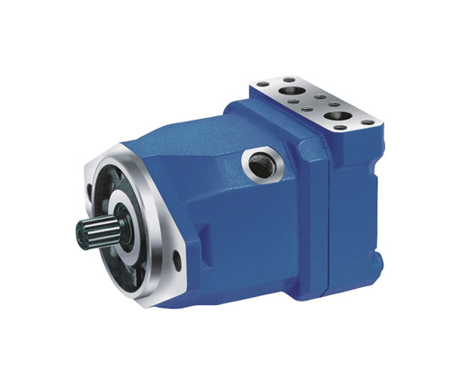
Axial piston fixed motor A10FM series 52
Well-tried A10 rotary group technology
Approved for high speeds
Long service life
High power density
Low operating noise
Optional with integrated anti-cavitation valve, e.g. for fan drives
Optional with speed sensor
Swashplate design

Table of values


Note
● The values in the table are theoretical values, without consideration of efficiencies and tolerances. The values are rounded.
● Exceeding the maximum or falling below the minimum permissible values can lead to a loss of function, a reduction in operational service life or total destruction of the axial piston unit. We recommend testing the loads by means of experiment or calculation / simulation and comparison with the permissible values.

Hydraulic fluids
The axial piston unit is designed for operation with mineral oil HLP according to DIN 51524.
Application instructions and requirements for hydraulic fluids should be taken from the following data sheets before the start of project planning:
● 90220: Hydraulic fluids based on mineral oils and related hydrocarbons
● 90221: Environmentally acceptable hydraulic fluids
For operation with environmentally acceptable fluids please consult us.
Viscosity and temperature of hydraulic fluids

Selection of hydraulic fluid
Bosch Rexroth evaluates hydraulic fluids on the basis of the Fluid Rating according to the technical data sheet 90235.
Hydraulic fluids with positive evaluation in the Fluid Rating are provided in the following technical data sheet:
● 90245: Bosch Rexroth Fluid Rating List for Rexroth hydraulic components (pumps and motors)
The hydraulic fluid should be selected so that the operating viscosity in the operating temperature range is within the optimum range (νopt; see selection diagram).
Selection diagram

Filtration of the hydraulic fluid
Finer filtration improves the cleanliness level of the hydraulic fluid, which increases the service life of the axial piston unit.
A cleanliness level of at least 20/18/15 is to be maintained according to ISO 4406.
At a hydraulic fluid viscosity of less than 10 mm²/s (e.g. due to high temperatures in short-term operation) at the drain port, a cleanliness level of at least 19/17/14 according to ISO 4406 is required.
For example, the viscosity is 10 mm²/s at:
● HLP 32 a temperature of 73°C
● HLP 46 a temperature of 85°C
Operating pressure range

Note
● Working pressure range valid when using hydraulic fluids based on mineral oils. Values for other hydraulic fluids, please contact us.
Permissible rotational speed in relation to outlet pressure

Pressure definition


Rate of pressure change

Direction of flow

Permissible radial and axial forces of the drive shaft

Sizes 23 and 28
Port plate 10


Port plate 16


Drive shafts

Ports

Sizes 37 and 45
Port plate 10

Port plate 16

Drive shafts

Ports

Sizes 58 and 63
Port plate 10

Port plate 16

Drive shafts

Ports

Installation instructions
General
● During commissioning and operation, the axial piston unit must be filled with hydraulic fluid and air bled. This must also be observed following a relatively long standstill as the axial piston unit may drain back to the reservoir via the hydraulic lines.
● The case drain fluid in the housing must be directed to the reservoir via the highest available drain port (L, L1).
● If a shared drain line is used for several units, make sure that the respective case pressure is not exceeded. The shared drain line must be dimensioned to ensure that the maximum permissible case pressure of all connected units is not exceeded in any operating conditions, specifically on cold start. If this is not possible, separate reservoir lines must be laid as required.
● To achieve favorable noise values, all connecting lines should be decoupled by using elastic elements and above-reservoir installation is to be avoided.
● In all operating conditions, the drain line must flow into the reservoir below the minimum fluid level.
Installation position
See the following examples 1 to 4.
Further installation positions are possible upon request. Recommended installation position: 1 and 2.
Below-tank installation (standard)
Below-tank installation is at hand if the axial piston unit is installed below the minimum liquid level outside the tank.


Above-reservoir installation
Above-reservoir installation means that the axial piston unit is installed above the minimum fluid level of the reservoir.


Note
● Connection F is part of the external piping and must be provided on the customer side to simplify the filling and bleeding.
General project planning notes
● The axial piston unit is designed to be used in open and closed circuits.
● The project planning, installation and commissioning of the axial piston unit require the involvement of qualified skilled personnel.
● Before using the axial piston unit, please read the corresponding instruction manual completely and thoroughly. If necessary, request it from Bosch Rexroth.
● Before finalizing your design, request a binding installation drawing.
● The specified datas and notes must be observed.
● Preservation: Our axial piston units are supplied as standard with preservative protection for a maximum of 12 months. If longer preservative protection is required (maximum 24 months), please specify this in plain text when placing your order. The preservation times are valid under optimal storage conditions. Details of these conditions can be found in the data sheet 90312 or the instruction manual.
● A pressure relief valve is to be provided in the hydraulic system.
● Observe the instructions in the instruction manual regarding tightening torques of connection threads and other threaded joints used.
● The notes in the instruction manual on tightening torques of the port threads and other screw joints must be observed.
● The ports and fastening threads are designed for the permissible maximum pressure pmax (see instruction manual). The machine or system manufacturer must ensure that the connecting elements and lines correspond to the specified operating conditions (pressure, flow, hydraulic fluid, temperature) with the necessary safety factors.
● The working ports and function ports are designated only to accommodate hydraulic lines.
● During and shortly after operation, there is a risk of burns on the axial piston unit. Take appropriate safety measures (e.g. by wearing protective clothing).