
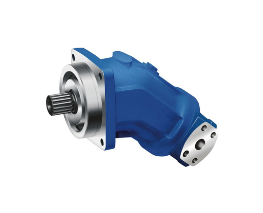
● Robust pump with long service life
● Very high total efficiency
● High power density
● Large variety of available nominal sizes allows exact adjustment to the application
● Optional with long-life bearings for the nominal sizes 250 to 1000
● Bent-axis design


Size 5

Drive shafts

Ports

Size 10 … 16

Drive shafts Z and A

Drive shafts P and B

Ports

Size 23 … 180


Drive shafts Z and A

Splined shaft DIN 5480

Drive shafts P and B

Parallel keyed shaft DIN 6885

Ports

Size 200

Drive shafts

Ports

Size 250

Drive shafts

Ports

Size 355 … 1000


Drive shaft Z

Splined shaft DIN 5480

Drive shaft P


Parallel keyed shaft DIN 6885

Ports

Installation instructions
General
● During commissioning and operation, the axial piston unit must be filled with hydraulic fluid and air bled. This must also be observed following a relatively long standstill as the axial piston unit may drain back to the reservoir via the hydraulic lines.
● Particularly in the installation position "drive shaft upwards" filling and air bleeding must be carried out completely as there is, for example, a danger of dry running.
● The case drain fluid in the housing must be directed to the reservoir via the highest available drain port (T1,T2).
● If a shared drain line is used for several units, make sure that the respective case pressure is not exceeded. The shared drain line must be dimensioned to ensure that the maximum permissible case pressure of all connected units is not exceeded in any operating conditions, specifically on cold start. If this is not possible, separate reservoir lines must be laid as required.
● To achieve favorable noise values, all connecting lines should be decoupled by using elastic elements and above-reservoir installation is to be avoided.
● In all operating conditions, the suction and drain lines must lead into the reservoir below the minimum fluid level. The permissible suction height hS results from the overall loss of pressure; it must not, however, be higher than hS max = 800 mm. The minimum suction pressure at port S must also not fall below 0,8 bar absolute during operation and during cold start.
● When designing the reservoir, ensure adequate space between the suction line and the drain line.This provides a slow-down and desgasification of the fluid and prevents that heated return flow is being drawn directly back into the suction line.
Installation position
See the following examples 1 to 8.
Further installation positions are possible upon request. Recommended installation position: 1 and 2.
Below-tank installation (standard)
Below-tank installation is at hand if the axial piston unit is installed below the minimum liquid level outside the tank.


Above-reservoir installation
Above-reservoir installation means that the axial piston unit is installed above the minimum fluid level of the reservoir.
Recommendation for installation position 8 (drive shaft upward): A check valve in the drain line (cracking pressure 0,5 bar) can prevent draining of the pump housing.


Note
● Connection F is part of the external piping and must be provided on the customer side to simplify the filling and bleeding.
General project planning notes
● The axial piston unit is designed to be used in open circuits.
● The project planning, installation and commissioning of the axial piston unit require the involvement of qualified skilled personnel.
● Before using the axial piston unit, please read the corresponding instruction manual completely and thoroughly. If necessary, request it from Bosch Rexroth.
● Before finalizing your design, request a binding installation drawing.
● The specified datas and notes must be observed.
● Preservation: Our axial piston units are supplied as standard with preservative protection for a maximum of 12 months. If longer preservative protection is required (maximum 24 months), please specify this in plain text when placing your order. The preservation times are valid under optimal storage conditions. Details of these conditions can be found in the data sheet 90312 or the instruction manual.
● A pressure relief valve is to be provided in the hydraulic system.
● Observe the instructions in the instruction manual regarding tightening torques of connection threads and other threaded joints used.
● The notes in the instruction manual on tightening torques of the port threads and other screw joints must be observed.
● The ports and fastening threads are designed for the permissible maximum pressure pmax (see instruction manual). The machine or system manufacturer must ensure that the connecting elements and lines correspond to the specified operating conditions (pressure, flow, hydraulic fluid, temperature) with the necessary safety factors.
● The working ports and function ports are only intended to accommodate hydraulic lines.
● During and shortly after operation, there is a risk of burns on the axial piston unit. Take appropriate safety measures (e.g. by wearing protective clothing).