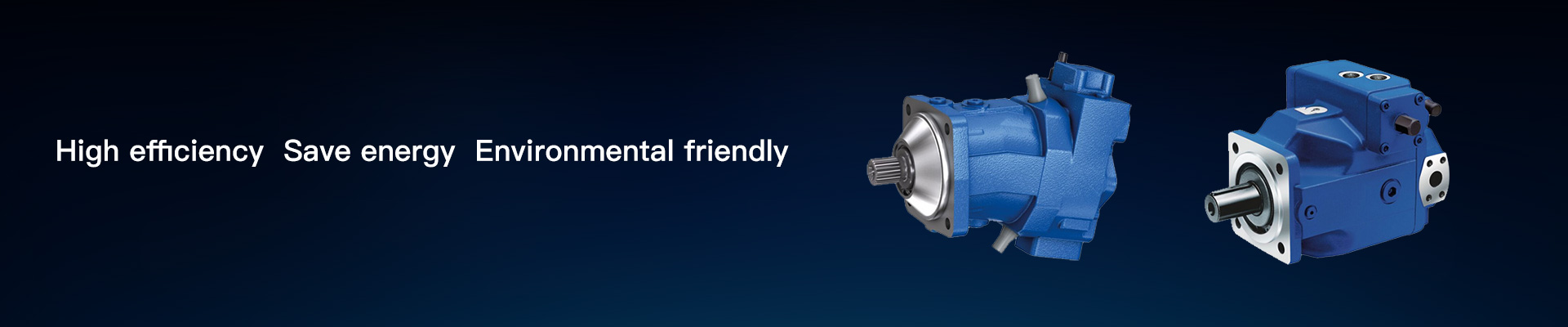
Significant fuel savings up to 15% compared to constant systems
Optimized efficiency, though same power at less fuel consumption
Increased service life compared to gear pumps
Compact design by integrated controller
A wide range of highly adaptable control devices for all important applications
Stepless flow variation by adjusting the swashplate angle.
Low operating noise
High power density
Excellent suction characteristics
High flexibility through interchangeable through drive adapters
Swashplate design


Notice
● Observe the information in the project planning notes chapter
● Observe the project planning notes regarding each control device
● In addition to the type code, please specify the relevant technical data when placing your order
Table of values


Notice
● The table values are theoretical values without consideration of efficiencies and tolerances. The values are rounded.
● Operation above the maximum values or below the minimum values may result in a loss of function, a reduced service life or in the destruction of the axial piston unit.
Bosch Rexroth recommends testing the loads by means of experiment or calculation / simulation and comparison with the permissible values.
Hydraulic fluid
The axial piston unit is designed for operation with HLP mineral oil according to DIN 51524. See the following data sheet for application instructions and requirements for selecting hydraulic fluid, behavior during operation as well as disposal and environmental protection before you begin project planning:
● 90220:Hydraulic fluids based on mineral oils and related hydrocarbons
Selection of hydraulic fluid
Bosch Rexroth evaluates hydraulic fluids on the basis of the Fluid Rating according to the technical data sheet 90235.
Hydraulic fluids with positive evaluation in the Fluid Rating are provided in the following technical data sheet:
● 90245: Bosch Rexroth Fluid Rating List for Rexroth hydraulic components (pumps and motors)
The hydraulic fluid should be selected so that the operating viscosity in the operating temperature range is within the optimum range (νopt; see selection diagram).
Viscosity and temperature of hydraulic fluids


Notice
The axial piston unit is not suitable for operation with water-free HF hydraulic fluids / HF hydraulic fluids containing water / HFx hydraulic fluids.
Filtration of the hydraulic fluid
Finer filtration improves the cleanliness level of the hydraulic fluid, which increases the service life of the axial piston unit.
A cleanliness level of at least 20/18/15 is to be maintained according to ISO 4406.
At a hydraulic fluid viscosity of less than 10 mm²/s (e.g. due to high temperatures in short-term operation) at the drain port, a cleanliness level of at least 19/17/14 according to ISO 4406 is required.
For example, the viscosity is 10 mm²/s at:
● HLP 32 a temperature of 73°C
● HLP 46 a temperature of 85°C
Operating pressure range

Pressure definition

Rate of pressure change

Notice
● Working pressure range applies when using mineral oil-based hydraulic fluids. Please contact us for values for other hydraulic fluids.
● In addition to the hydraulic fluid and the temperature, the service life of the shaft seal is influenced by the rotational speed of the axial piston unit and the case pressure.
● The case pressure must be greater than the ambient pressure.
Permissible radial and axial forces of the drive shaft


Distribution of torques

Permissible input and through-drive torques

Notice
The values given are maximum values and do not apply to continuous operation. All shaft loads reduce the bearing service life!
Sizes 18 and 28
Dimensions, sizes 18 and 28
DR, DN - Pressure controller
DRS0, DNS0 - Pressure controller with load-sensing,
Clockwise rotation


Sizes 18 and 28
DR, DN - Pressure controller
DRS0, DNS0 - Pressure controller with load-sensing,
Counter-clockwise rotation

Splined shaft SAE J744

Keyed shaft

D3/D4 Pressure controller with override, electric-proportional

Ports and fastening threads version "B"

Ports and fastening threads version "M"


Size 35
Dimensions, sizes 18 and 28
DR, DN - Pressure controller
DRS0, DNS0 - Pressure controller with load-sensing,
Clockwise rotation

Size 35
DR, DN - Pressure controller
DRS0, DNS0 - Pressure controller with load-sensing,
Counter-clockwise rotation

Splined shaft SAE J744

D3/D4 Pressure controller with override, electric-proportional

Ports and fastening threads version "B"

Ports and fastening threads version "M"

Notice:
At all ports - in particular when connecting port S - use the stud ends provided for the standard with the corresponding width across flats. Please contact us about larger widths across flats.
Dimensions for through drives

2-bolt flange ⌀82.55 mm, SAE J744 82-2 (A)


2-bolt flange ⌀101.6mm, SAE J744 101-2 (B)

Overview of mounting options

Combination pumps A1VO + A1VO
By using combination pumps, it is possible to have independent circuits without the need for splitter gearboxes.
When ordering combination pumps, the type designations of the 1st and 2nd pumps must be linked by a "+".
Order example:
A1VO035DRS0C200/10BRVB2S51B2S500-0+
A1VO035DRS0C200/10BRVB2S51000000-0
A tandem pump, with two pumps of equal size, is permissible without additional supports, assuming that the dynamic mass acceleration does not exceed a maximum of 10 g (= 98.1 m/s2).
For combination pumps consisting of more than two pumps, the mounting flange must be calculated for the permissible mass torque.


Total length A

Permissible moments of inertia

Installation instructions
General
The axial piston unit must be filled with hydraulic fluid and air bled during commissioning and operation. This must also be observed following a longer standstill as the axial piston unit may empty via the hydraulic lines.
Particularly in installation position "Drive shaft upwards/downwards", complete filling and air bleeding must be ensured as there is for example a risk of dry running.
The leakage in the housing area must be drained via the highest leakage port (L1, L2) to the reservoir.
In case of combinations of several units, draining of leakage is required at all pumps.
If one common drain line is used for several units, it must be ensured that the respective case pressure is not exceeded. The shared drain line must be dimensioned to ensure that the maximum permissible case pressure of all connected units is not exceeded in any operating conditions, particularly at cold start. If this is not possible, separate drain lines must be laid, if necessary.
To achieve favorable noise values, decouple all connecting lines using elastic elements and avoid above-reservoir installation.
In all operating conditions, the suction and drain lines must flow into the reservoir below the minimum fluid level. The permissible suction height hS is derived from the total pressure loss. However, hS max = 800 mm must not be exceeded. The minimum suction pressure at port S must also not fall below 0.8 bar abs. during operation and during a cold start.
Make sure to provide adequate distance between suction line and drain line for the reservoir design. This prevents the heated return flow from being drawn directly back into the suction line.
Notice
● Port F is part of the external piping and must be provided on the customer side to make filling and air bleeding easier.
● In certain installation positions, an influence on the adjustment or control can be expected.
Gravity, dead weight and case pressure can cause minor characteristic shifts and changes in actuating time.
Installation position
See the following examples 1 to 11.
Further installation positions are available upon request.
Installation positions 1 and 2 are recommended.
Below-reservoir installation (standard)
Below-reservoir installation is when the axial piston unit is installed outside of the reservoir below the minimum fluid level.


Inside-reservoir installation
Inside-reservoir installation is when the axial piston unit is installed in the reservoir below the minimum fluid level.
The axial piston unit is completely below the hydraulic fluid.
If the minimum fluid level is equal to or below the upper edge of the pump, see chapter "Above-reservoir installation".
Axial piston units with electrical components (e.g. electric control, sensors) may not be installed in a reservoir below the fluid level.


Project planning notes
● The axial piston unit is designed to be used in open circuits.
● The project planning, assembly and commissioning of the axial piston unit require the involvement of qualified skilled persons.
● Before using the axial piston unit, please read the corresponding instruction manual completely and thoroughly. If necessary, this can be requested from Bosch Rexroth.
● Before finalizing your design, please request a binding installation drawing.
● The specified data and notes contained herein must be observed.
● Depending on the operating conditions of the axial piston unit (working pressure, fluid temperature), the characteristic curve may shift.
● The characteristic curve may also shift due to the dither frequency or control electronics.
● Preservation: Our axial piston units are supplied as standard with preservative protection for a maximum of 12 months. If longer preservation is required (maximum 24 months), please specify this in plain text when placing your order. The preservation periods apply under optimal storage conditions, which can be found in data sheet 90312 or in the instruction manual.
● Not all versions of the product are approved for use in a safety function according to ISO 13849. Please consult the proper contact at Bosch Rexroth if you require reliability parameters (e.g. MTTFd) for functional safety.
● Depending on the type of control used, electromagnetic effects can be produced when using solenoids. Use of the recommended direct current (DC) on the electromagnet does not produce any electromagnetic interference (EMI) nor is the electromagnet influenced by EMI. Potential electromagnetic interference (EMI) exists if the solenoid is energized with a modulated direct current (e.g. PWM signal). The machine manufacturer should conduct appropriate tests and take appropriate measures to ensure that other components or operators (e.g. with a pacemaker) are not affected by this potentiality.
● Pressure controllers are no safeguards against pressure overload. Be sure to add a pressure relief valve to the hydraulic system.
● For drives that are operated for a long period with constant rotational speed, the natural frequency of the hydraulic system can be stimulated by the excitation frequency of the pump (rotational speed frequency ×9). This can be prevented with suitably designed hydraulic lines.
● Please note the details regarding the tightening torques of port threads and other threaded joints in the instruction manual.
● The ports and fastening threads are designed for the specified maximum pressure. The machine or system manufacturer must ensure the connecting elements and lines correspond to the specified application conditions (pressure, flow, hydraulic fluid, temperature) with the necessary safety factors.
● The working ports and function ports are only intended to accommodate hydraulic lines.
Safety instructions
● During and shortly after operation, there is a risk of burns on the axial piston unit and especially on the solenoids. Take the appropriate safety measures (e.g. by wearing protective clothing).
● Moving parts in control equipment (e.g. valve spools) can, under certain circumstances, get stuck in an undefined position as a result of contamination (e.g. contaminated hydraulic fluid, abrasion, or residual dirt from components). As a result, the hydraulic fluid flow and the build-up of torque in the axial piston unit can no longer respond correctly to the operator’s specifications. Even the use of various filter elements (external or internal flow filtration) will not rule out a fault but merely reduce the risk. The machine/system manufacturer must test whether remedial measures are needed on the machine for the application concerned in order to bring the driven consumer into a safe position (e.g. safe stop) and ensure any measures are properly implemented.