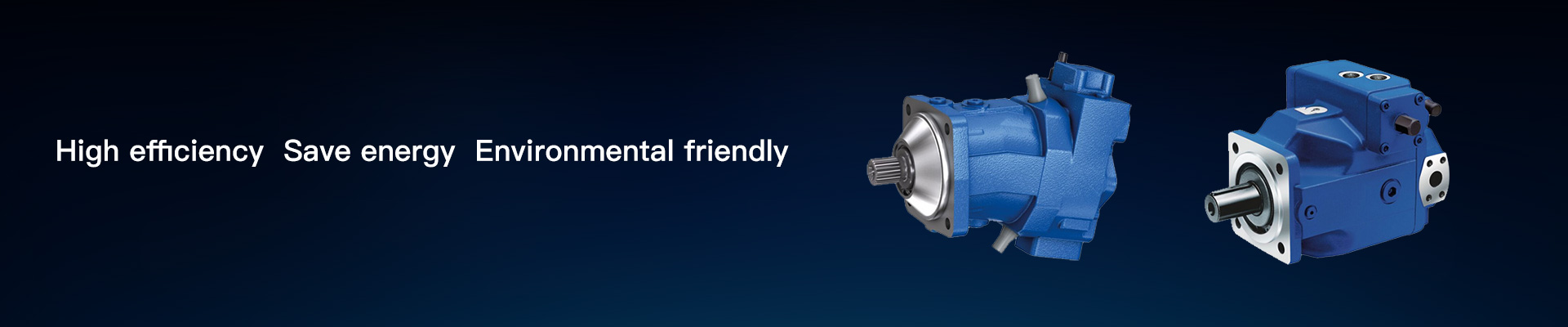
Nominal pressure range up to 350 bar for reduced operation data possible.
High permissible drive speed
Favorable power-to-weight ratio – compact dimensions
Low noise
Excellent suction characteristics
Controls with short response times
Swashplate design


Notice
● Observe the information in the project planning notes chapter
● Observe the project planning notes regarding each control device
● In addition to the type code, please specify the relevant technical data when placing your order
Table of values


Notice
●The table values are theoretical values without consideration of efficiencies and tolerances. The values are rounded.
●Operation above the maximum values or below the minimum values may result in a loss of function, a reduced service life or in the destruction of the axial piston unit.
Bosch Rexroth recommends testing the loads by means of experiment or calculation / simulation and comparison with the permissible values.
Hydraulic fluid
The axial piston unit is designed for operation with HLP mineral oil according to DIN 51524. See the following data sheet for application instructions and requirements for selecting hydraulic fluid, behavior during operation as well as disposal and environmental protection before you begin project planning:
●90220:Hydraulic fluids based on mineral oils and related hydrocarbons
Selection of hydraulic fluid
Bosch Rexroth evaluates hydraulic fluids on the basis of the Fluid Rating according to the technical data sheet 90235.
Hydraulic fluids with positive evaluation in the Fluid Rating are provided in the following technical data sheet:
●90245: Bosch Rexroth Fluid Rating List for Rexroth hydraulic components (pumps and motors)
The hydraulic fluid should be selected so that the operating viscosity in the operating temperature range is within the optimum range (νopt; see selection diagram).
Viscosity and temperature of hydraulic fluids

Selection diagram

Notice
For applications in the low-temperature range down to -40°C, please contact us.
Filtration of the hydraulic fluid
Finer filtration improves the cleanliness level of the hydraulic fluid, which increases the service life of the axial piston unit.
A cleanliness level of at least 20/18/15 is to be maintained according to ISO 4406.
At a hydraulic fluid viscosity of less than 10 mm²/s (e.g. due to high temperatures in short-term operation) at the drain port, a cleanliness level of at least 19/17/14 according to ISO 4406 is required.
For example, the viscosity is 10 mm²/s at:
●HLP 32 a temperature of 73°C
●HLP 46 a temperature of 85°C
Operating pressure range


Rate of pressure change

Pressure definition

Notice
●Working pressure range applies when using mineral oil-based hydraulic fluids. Please contact us for values for other hydraulic fluids.
Permissible radial and axial loading of the drive shaft
Notice
●For drives with radial loading (pinion, V-belt drives), please contact us!
●For drives with axial loading drives, please contact us!
Permissible input and through-drive torques

Distribution of torques


Size 145
DRC – Pressure flow controller
Clockwise rotation
Mounting flange C2 (SAE-C; 127-2)1)

Size 145
DRC – Pressure flow controller
Clockwise rotation
Mounting flange D4 (SAE-D; 152-4)1)

Size 145
EP4DR – Electro-proportional control with pressure controller
Clockwise rotation
Mounting flange G3 (SAE J617)1)

Splined shaft SAE J744

Splined shaft SAE J744

Ports and fastening threads port plate 02

Controller variants
All versions with:
Port plate 02; mounting flange D4; clockwise rotation
DR - Pressure controller

DRC – Pressure flow controller

EP4DR – Electro-proportional control with pressure controller

Dimensions for through drives BxSx


2-hole flange ⌀127 mm, SAE J744 127-2 (C)


Overview of mounting options

Notice
A10VOH may only be planned as pump compensation without support with 100% through drive if the 1st pump is general provided with a 152-4 or 409-12 mounting flange (type code designation D4 or G3).
Combination pumps A10VOH + A10VOH
By using combination pumps, it is possible to have independent circuits without the need for splitter gearboxes.
When ordering combination pumps, the type designations of the 1st and 2nd pump must be connected with a "+" and are combined into one part number. Each single pump should be ordered according to type code.
Notice
The combination pump type code is shown in shortened form in the order confirmation.
Example:
A10VOH 145 DRS00/60BR+A10VOH 145 DRS00/60BR
Each through drive is plugged with a non–pressure-resistant cover. This means the units must be sealed with a pressure-resistant cover before commissioning. Through drives can also be ordered with a pressure-resistant cover (U000).
Order example:
A10VOH145DRC0/60BRVD4R112D4R1+
A10VOH145DRC0/60BRVD4R112U000
A tandem pump with two pumps of equal size is permissible without additional supports, assuming that the dynamic mass acceleration does not exceed maximum 10 g (= 98.1 m/s2).
For combination pumps consisting of more than two pumps, the mounting flange must be rated for the permissible mass torque (please contact us).


Weight with mounting flange C2, D4 and G3